

 CN

Multi-Channel HDMI HD Video Surveillance Decoder Matrix: DS-6A01UD / 6A04UD / 6A06UD / 6A08UD
A surveillance system does not fail at the camera. It fails at the wall. When dozens of streams need to land on a controlled set of screens inside a control room, a command centre or a retail loss-prevention desk, the decoder matrix is the component that decides whether operators see the right picture at the right time — or a tangle of scrolling tiles they cannot read.
The new multi-channel HDMI HD video surveillance decoder matrix series (DS-6A01UD, 6A04UD, 6A06UD and 6A08UD) is built for exactly that job. It is a 2-screen HD decoder matrix with splicing and multi-window control built in, delivering 16 HDMI outputs, 48 VGA outputs, 8 BNC outputs and 8 alarm inputs / 8 alarm outputs from a single 450 mm chassis. This article walks through what it does, where it fits, and how to choose the right variant for a project.
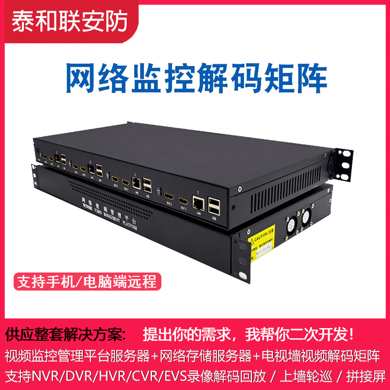
Why the Decoder Matrix Decides Whether a Video Wall Works
In most control-room projects, the cameras are specified first, the recorder second, and the display layer last. That ordering is backwards. The decoder matrix defines how many independent pictures can be shown, how many operators can view different content at the same time, and how easily the layout can be rearranged when an incident occurs. A decoder that runs out of outputs silently caps the value of every camera installed upstream of it.
This series was specified for projects that need a large number of simultaneous display channels without stacking multiple standalone decoders across a rack. With 16 HDMI outputs, 48 VGA outputs and 8 BNC outputs, it provides display capacity across digital, analogue-replacement and legacy composite monitor tiers from one device.
At-a-Glance Specifications
| Parameter | Value |
|---|---|
| Product type | Multi-channel HDMI HD video surveillance decoder matrix |
| Model numbers | DS-6A01UD / DS-6A04UD / DS-6A06UD / DS-6A08UD |
| Configuration | 2-screen HD decoder matrix with integrated splicing (video wall) control |
| HDMI outputs | 16 |
| VGA outputs | 48 |
| BNC outputs | 8 |
| Audio outputs | 16 |
| Input interfaces | 8 |
| Network interface | 1 |
| Alarm inputs | 8 |
| Alarm outputs | 8 |
| Combined decoding (stream merging) | Not supported |
| Wi-Fi | Not supported |
| Power supply | External, 220 V |
| Power consumption | 45 W |
| Operating temperature | -20 °C to 75 °C |
| Operating humidity | 35 % |
| Dimensions | 450 mm |
| Weight | 22.3 kg |
| Place of origin | China |
16 HDMI Outputs, 48 VGA Outputs, 8 BNC Outputs: One Device, Three Display Tiers
The most striking feature of this decoder matrix is that the output stage is not limited to a single connector type. Each tier serves a distinct purpose in a real installation:
- 16 HDMI outputs — the primary digital layer. These drive the main video wall, HD operator monitors and presentation screens with full digital image quality, with no conversion hardware in the path.
- 48 VGA outputs — the high-density secondary layer. This is where the platform pulls ahead of typical decoders, allowing a large number of VGA-capable monitors, legacy control-room displays or distribution points to be fed from the same decoder rather than from a separate matrix.
- 8 BNC outputs — the composite tier. BNC remains the practical interface for analogue monitors, spot monitors at guard stations, and video feeds to older peripheral equipment that has not yet been refreshed.
- 16 audio outputs — audio follows the video path, so monitored channels can carry sound to the operator position or be routed to an announcement system.
The practical result is consolidation. A project that would otherwise require a digital decoder, a VGA matrix and a BNC distribution amplifier can be served from one 450 mm chassis with one power connection and one set of configuration tools.
Built-In Splicing and Multi-Window Control
This is a 2-screen HD decoder matrix with splicing control integrated into the unit. That detail matters more than it first appears. Traditionally, creating a seamless video wall or a custom multi-window layout requires a separate splicing processor sitting between the decoders and the screens. Every added box adds a power point, a firmware version to track, a signal conversion step and one more thing that can fail during an incident.
With the splicing controller built in, the decoder matrix itself handles the composition: window placement, screen spanning and layout switching are managed inside the same chassis that decodes the streams. For integrators, that means:
- Shorter commissioning time — one device to address, configure and document.
- Fewer rack units and less cabling between the decode stage and the display stage.
- No interoperability questions between third-party splicing processors and the decoder output format.
- Simpler support after handover, because the display chain has a single vendor and a single configuration file.
Note that combined decoding (stream merging) is not supported on this series. Stream layout should be planned on a one-to-one channel mapping basis, which keeps the design predictable and makes post-installation troubleshooting straightforward.
8 Alarm Inputs and 8 Alarm Outputs for Peripheral Integration
The unit ships with 8 alarm inputs and 8 alarm outputs alongside 8 input interfaces. In operational terms, the alarm inputs let the decoder respond to external triggers — door contacts, intrusion panels, push buttons — while the alarm outputs can drive annunciators, relays or interlock equipment. For sites that need a decoder to be part of a coordinated response rather than a passive display device, these dry-contact interfaces are often the difference between an integrated system and a screen that simply shows pictures.
Engineered for Continuous Control-Room Operation
Decoder matrices are rarely switched off. They run through summer heat, overnight duty cycles and years of continuous service. The environmental and electrical ratings on this series reflect that reality:
- Operating temperature: -20 °C to 75 °C. A wide window that covers both cold unheated equipment rooms and the elevated internal temperatures of densely packed racks.
- Power consumption: 45 W. Low for a device driving this many output channels, which reduces heat load inside the cabinet and eases the sizing of UPS backup capacity.
- External 220 V power supply. The power conversion stage sits outside the chassis, keeping heat and electrical noise away from the decoding electronics and making replacement a plug-and-play service action rather than a bench repair.
- 450 mm chassis, 22.3 kg. A compact footprint that fits standard rack planning without consuming the space of several stacked standalone decoders.
- Operating humidity rated at 35 %. The unit is intended for controlled equipment rooms and cabinets, where humidity is managed — a normal and sensible assumption for a control-room device.
A Security-First Network Position
The network interface count is one, and Wi-Fi is not supported. In a surveillance environment, both facts are advantages rather than limitations. A single wired Ethernet connection gives the decoder a clearly defined and easily documented position in the network topology: one IP address, one firewall rule, one VLAN assignment recorded in the as-built drawings. Because there is no wireless radio, there is no hidden access path into the display layer, and no risk of the decoder bridging a secure camera VLAN to an unmanaged wireless segment.
For projects with auditors, security consultants or compliance reviews in the loop, a decoder that cannot be reached over Wi-Fi is a simpler thing to defend than one that can.
Typical Deployment Scenarios
- Campus and industrial park control rooms — 16 HDMI outputs for the main wall, VGA outputs for distributed departmental monitors, BNC for guardhouse spot monitors.
- Transport and traffic operations centres — high channel counts plus alarm inputs for incident-triggered layout switching.
- Retail and chain-store loss prevention — a compact chassis feeding a small wall plus multiple back-office displays.
- Energy, utilities and manufacturing — wide temperature tolerance for plant-side equipment rooms that are not fully climate-controlled.
- Financial and government premises — isolated wired network, alarm contact integration, and a display chain with a single point of configuration.
Choosing Between DS-6A01UD, 6A04UD, 6A06UD and 6A08UD
The series is offered under four ordering codes — DS-6A01UD, DS-6A04UD, DS-6A06UD and DS-6A08UD — so that a single platform can be matched to different channel-count and cabinet requirements across a project portfolio. The most reliable way to select is to work backwards from the display plan rather than forwards from the camera count:
- Count the displays that must show live surveillance pictures at the same time — that figure sets the practical floor for output capacity.
- Separate the displays by connector type: HDMI for HD walls and operator positions, VGA for legacy and distributed monitors, BNC for analogue spot monitors.
- Decide whether the wall needs splicing and multi-window composition. If it does, confirm that the built-in controller is used rather than adding an external processor.
- List the external triggers and outputs the site needs, and map them to the 8 alarm inputs and 8 alarm outputs.
- Check the equipment room's temperature and humidity envelope against the -20 °C to 75 °C operating range and the 35 % humidity rating.
- Confirm rack space and rack depth against the 450 mm chassis and 22.3 kg weight, and verify that an external 220 V supply point is available.
The Bottom Line
This multi-channel HDMI HD video surveillance decoder matrix is designed around a simple idea: the display layer should not be the bottleneck. With 16 HDMI outputs, 48 VGA outputs, 8 BNC outputs, 16 audio outputs, built-in splicing control, 8 alarm inputs and 8 alarm outputs in a single 450 mm chassis drawing just 45 W, it replaces a stack of separate decoders, matrices and splicing processors with one documented, serviceable device.
For integrators tired of commissioning four boxes to do one job, and for end users tired of explaining why a screen went dark during an incident, the DS-6A01UD / 6A04UD / 6A06UD / 6A08UD series is worth specifying early — before the display layout is locked, not after.